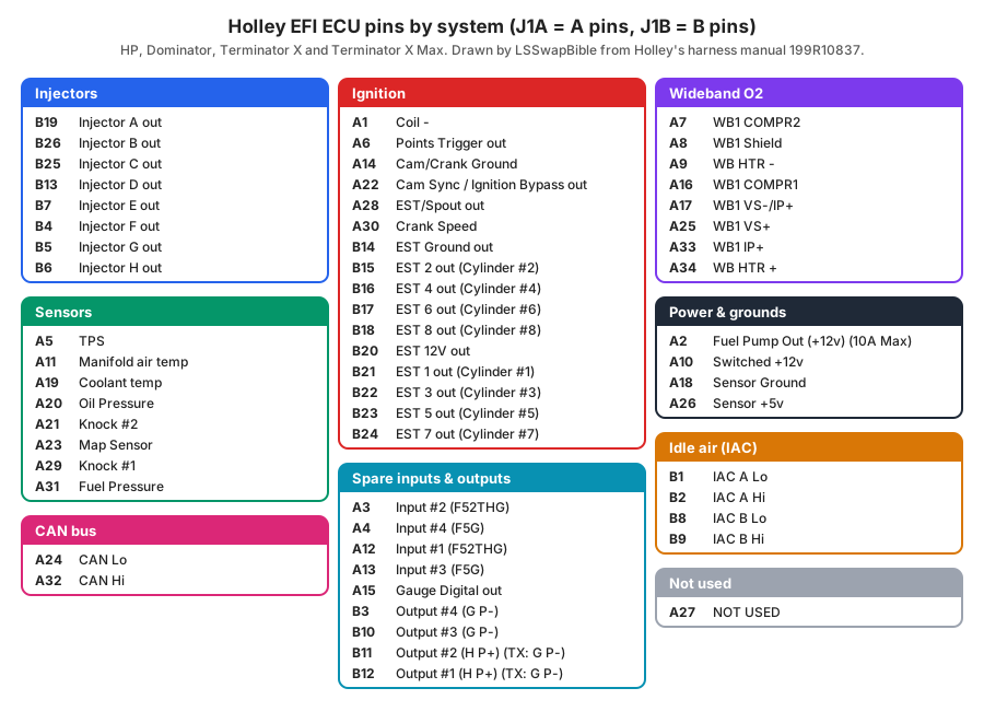
The Holley HP, Dominator, Terminator X and Terminator X Max share the same J1A and J1B pinout. Use this when you're tracing a wire, adding a sensor or checking a harness. The connector and loose-wire tables below are for Holley's 558-503, 558-504 and 558-508 harness kits.
Pins by system
J1A connector
Pin
Function
A1
Coil - Input
A2
Fuel Pump Out (+12v) (10A Max)
A3
Input #2 (F52THG)
A4
Input #4 (F5G)
A5
TPS Input
A6
Points Trigger Output
A7
WB1 COMPR2
A8
WB1 Shield
A9
WB HTR -
A10
Switched +12v Input
A11
Manifold Air Temp Input
A12
Input #1 (F52THG)
A13
Input #3 (F5G)
A14
Cam/Crank Ground
A15
Gauge Digital Output
A16
WB1 COMPR1
A17
WB1 VS-/IP+
A18
Sensor Ground
A19
Engine Coolant Temp Input
A20
Oil Pressure Input
A21
Knock #2 Input
A22
Cam Sync Input / Ignition Bypass Output
A23
Map Sensor Input
A24
CAN Lo
A25
WB1 VS+
A26
Sensor +5v
A27
NOT USED
A28
EST/Spout Output
A29
Knock #1 Input
A30
Crank Speed Input
A31
Fuel Pressure Input
A32
CAN Hi
A33
WB1 IP+
A34
WB HTR +
J1B connector
Pin
Function
B1
IAC A Lo
B2
IAC A Hi
B3
Output #4 (G P-)
B4
Injector F Output
B5
Injector G Output
B6
Injector H Output
B7
Injector E Output
B8
IAC B Lo
B9
IAC B Hi
B10
Output #3 (G P-)
B11
Output #2 (H P+) for HP and Dominator, (G P-) for Terminator X and X Max
B12
Output #1 (H P+) for HP and Dominator, (G P-) for Terminator X and X Max
B13
Injector D Output
B14
EST Ground Output
B15
EST 2 Output (Cylinder #2)
B16
EST 4 Output (Cylinder #4)
B17
EST 6 Output (Cylinder #6)
B18
EST 8 Output (Cylinder #8)
B19
Injector A Output
B20
EST 12V Output
B21
EST 1 Output (Cylinder #1)
B22
EST 3 Output (Cylinder #3)
B23
EST 5 Output (Cylinder #5)
B24
EST 7 Output (Cylinder #7)
B25
Injector C Output
B26
Injector B Output
B11 and B12 differ by ECU: high-side (H, P+) outputs on the HP and Dominator, ground-side (G, P−) on the Terminator X and X Max.
Harness connectors
Injector connector (A = cylinder 1 … H = cylinder 8)
Cavity
Circuit
ECU pin
A
Injector A Output - Cylinder #1
B19
B
Injector B Output - Cylinder #2
B26
C
Injector C Output - Cylinder #3
B25
D
Injector D Output - Cylinder #4
B13
E
Injector E Output - Cylinder #5
B7
F
Injector F Output - Cylinder #6
B4
G
Injector G Output - Cylinder #7
B5
H
Injector H Output - Cylinder #8
B6
J
+12V Power
K
+12V Power
Holley routes A–H to cylinders 1–8. Don't re-pin for firing order; the firing order is set in the software.
Ignition adapter connector
Cavity
Circuit
ECU pin
A
Crank signal Input - digital and inductive
A30
B
Cam signal Input / Ignition Bypass Output (bypass output for computer-controlled GM HEI)
* Holley's manual has three labeling slips we kept visible: the oil pressure section prints pin C as "Fuel Pressure Signal" (the ECU pin, A20, is the oil pressure input); the wideband section prints "CCOMPR2" (J1A table: COMPR2); and A17 reads "VS-/IP-" in the wideband section but "VS-/IP+" in the J1A table. Pin numbers agree everywhere.
Loose wires on the main harness
Wire
Color
Connect to
12V Switched
red/white
Connect to clean +12V active in ignition on and crank
12V Battery
red
Direct to battery; 20A fuse holder attached; powers fuel pump and injectors
12V Fuel Pump
green
Powers fuel pump directly (+12V); 14 gauge; not for pumps drawing over 10-12 amps
Points Output
white
Triggers CD ignition box
Ignition/DIS Chassis Ground
black
Connect to ground point common with engine and battery
Coil −
yellow
RPM input signal when not controlling timing and not running a CD ignition; do NOT connect to coil of a CD ignition (damages ECU)
Warning from Holley: never connect the yellow "Coil −" wire to the coil of a capacitive-discharge (MSD-type) ignition; it damages the ECU.